Space Station — Reference Architecture
Life-support, thermal, power and pressure-isolation systems
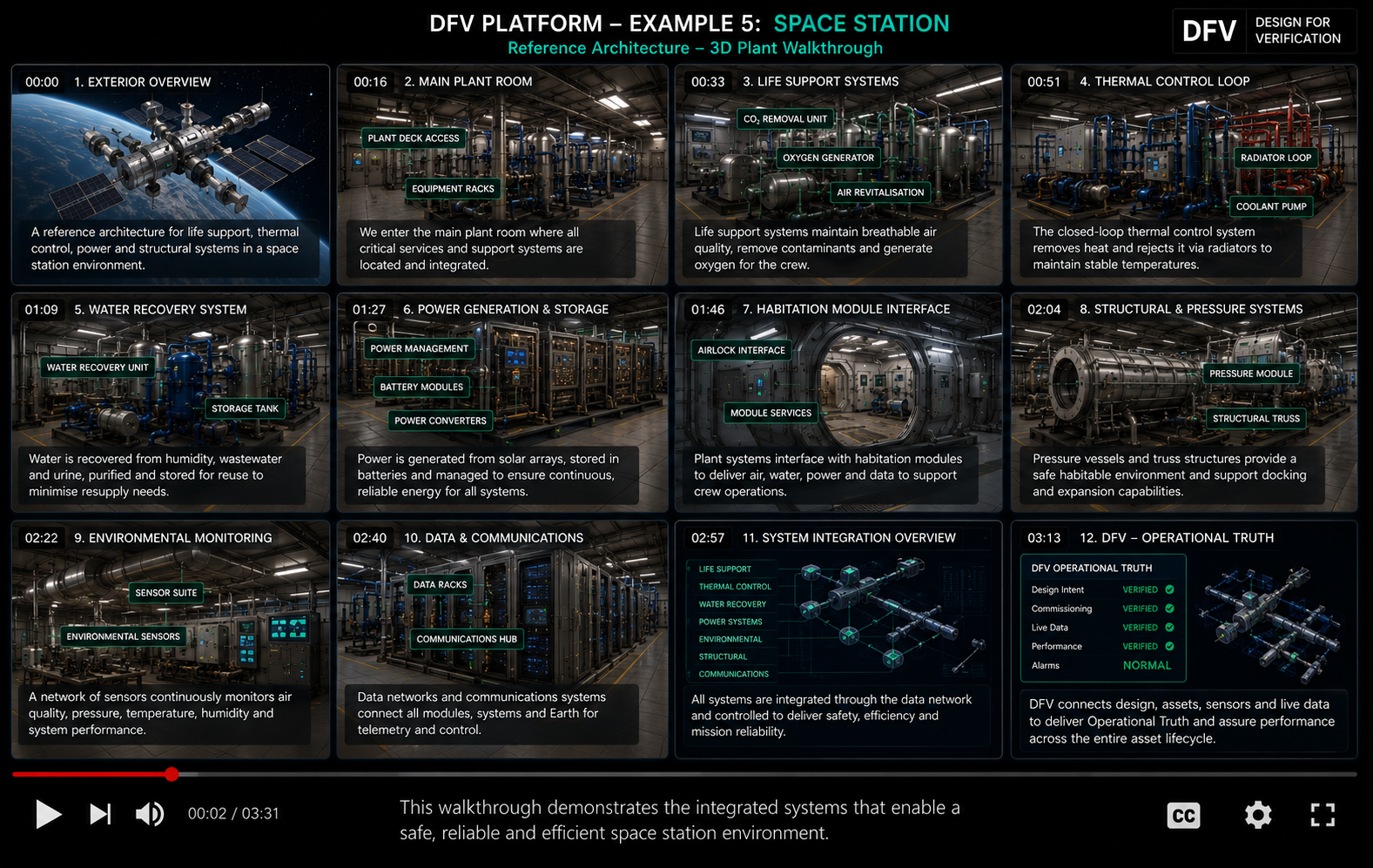
Plant overview
- Internal and external thermal control
- Atmosphere revitalisation and oxygen generation
- Water recovery
- Regenerative O₂/H₂O/CO₂ loop
- Electrical resilience, fire/pressure isolation and vacuum utilities
DFV connects each design requirement to identifiable assets, sensors, tests, documentation and operational evidence.
How it works
The system architecture is presented as connected engineering functions rather than isolated equipment. Plant, distribution, controls and end-use conditions are linked through a structured DFV evidence chain.
Lifecycle purpose
Commissioning evidence establishes the initial verified state. Operational data and governed change management support later re-verification.
Engineering sizing basis
Sizing is mission-based: crew metabolic loads, avionics/payload heat, environmental loads, recovery efficiencies, storage margin, orbital generation/eclipse profile, redundancy and contingency philosophy.
All figures shown in the demonstrations are concept/reference duties unless explicitly identified otherwise.
Reference basis
Applicable editions, project specifications, authority requirements and specialised standards must always be confirmed for a real project.
What DFV verifies
- Redundancy independence
- Mass/energy balance evidence
- Atmosphere and water recovery performance
- Power criticality/load shedding
- Pressure boundary and isolation status